
Electrode Base Platform
Electrode Base Platform
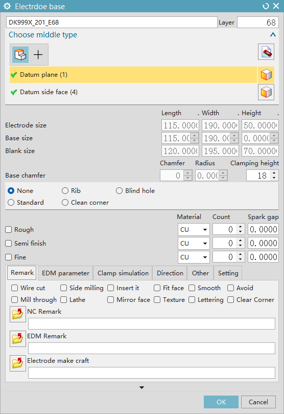
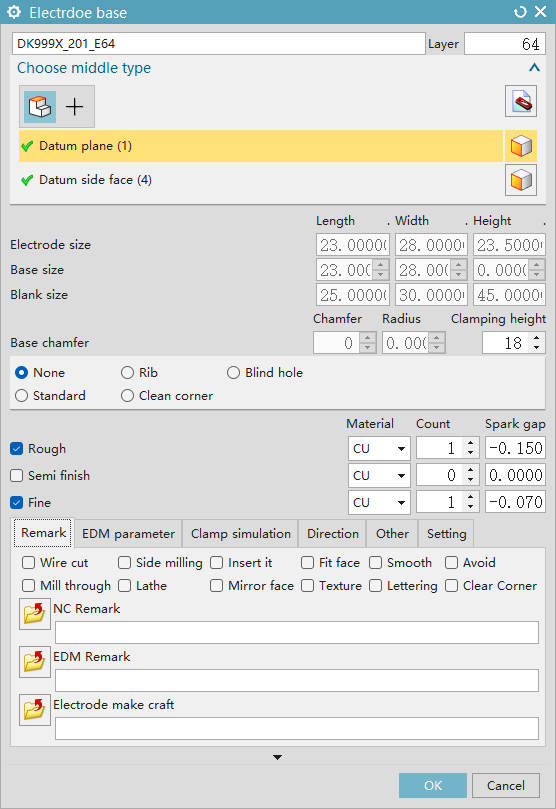
Electrode Base
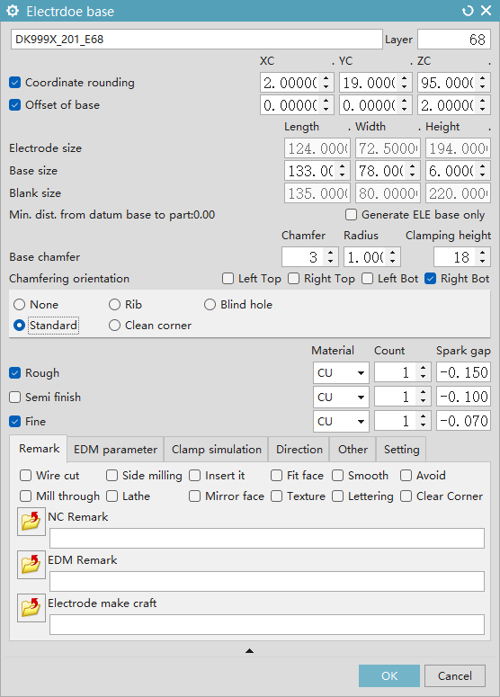
- Electrode Base: Create an electrode base platform based on the electrode feature and define relevant parameters
- Electrode Number: Define the electrode number (automatically generated based on the initialized electrode number prefix)
- Layer: Define the layer number for placing the electrode (start layer is defined according to system parameter settings)
- Discharge Coordinate Rounding: Define whether to round coordinates and adjust X, Y, Z values
- Base Platform Offset: Define the offset value of the base platform; the value is inherited by the next electrode
- Electrode Dimension: Display the external dimension of the electrode head
- Base Dimension: Define the dimension of the electrode base (supports system parameters to define minimum dimension and the distance from the reference edge to the feature)
- Blank Size: Display the blank size (supports system parameters to define expansion value and increment method)
- Minimum Distance from Base Platform to Part: Display the minimum distance between the base platform and the workpiece
- Generate Base Platform Only: Generate a base platform without attributes
- Reference Chamfer/Fillet: Adjust the size of chamfer (C-angle) and fillet (supports system parameters to define default size)
- Clamping Height: Adjust the electrode clamping height (supports system parameters to define default size)
- Reference Angle Orientation: Define the direction of the reference angle (supports system parameters to define default direction or inherit the previous direction)
- None, Standard, Rib: Combine spark gaps (supports system parameters to define combinations)
- Roughing: Define the quantity, gap, and material for roughing
- Semi-Finishing: Define the quantity, gap, and material for semi-finishing
- Finishing: Define the quantity, gap, and material for finishing
Remarks
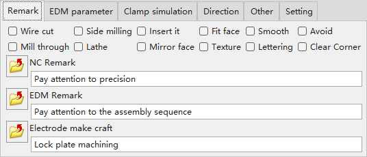
- CNC Machining Remarks: Remarks for CNC machining precautions, used for label output (supports system parameter settings)
- EDM Discharge Remarks: Remarks for EDM discharge precautions, used for label output (supports system parameter settings)
- Electrode Process Remarks: Remarks for process information precautions, used for label output (supports system parameter settings)
Discharge Parameters
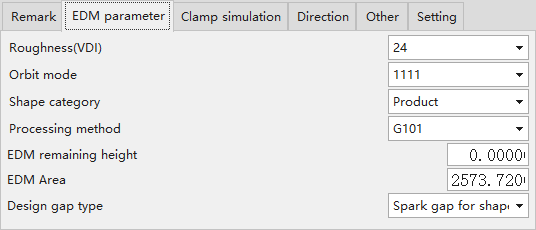
- Surface Roughness (VDI): Define surface roughness for label output (supports system parameters to set default value)
- Oscillation Mode: Define the oscillation mode for label output (supports system parameters to set default value)
- Shape Category: Define the electrode shape for label output (supports system parameters to set default value)
- Discharge Remaining Height: Define the actual discharge height
- Projected Discharge Area: Define the projected discharge area
Clamping Simulation
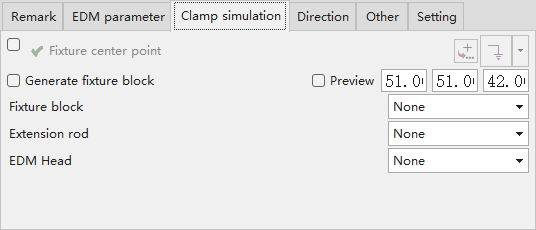
- Fixture Center Point: Define the fixture center point (correction for original text error: not surface roughness, but fixture center * point) for label output (supports system parameters to set default value)
- Generate Fixture Block: Define the fixture center, generally used for eccentric electrodes
- Preview: View the fixture model or custom block
- Clamping Block: Select the simulated clamping block
- Extension Rod: Select the simulated extension rod
- EDM Spindle Head: Select the simulated EDM spindle head
Direction
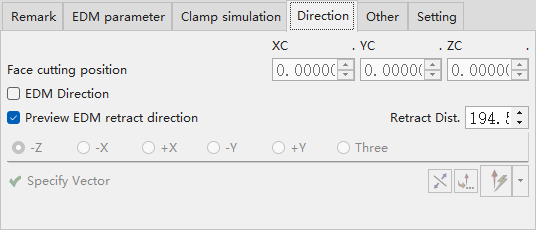
- Cutting Edge Reference Position: Adjust the 3-axis (XC, YC, ZC) linked cutting edge position
- Electrode Discharge Direction: After activating the discharge direction, it can be modified to -Z, -X, +X, -Y, +Y, Three (3-axis direction)
- Preview Discharge Retract Direction: View the electrode retract position
- Retract Distance: Set the electrode retract distance
Others
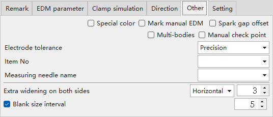
- Mark Special Color: Bind a unique color ID to the electrode
- Mark Manual Discharge: After marking manual discharge, no program will be generated for scan discharge
- Mark Gap-Adjusted Body: Mark that the electrode gap has been adjusted
- Roughing-Finishing Multi-Tooth Electrode: Automatically jump to the roughing-finishing multi-tooth electrode settings
- Manual Point Acquisition: Mark that the electrode feature will not automatically acquire points
- Tolerance Type: Modify the electrode tolerance
- Material Number: Connect to the Manufacturing Execution System (MES)
- Measuring Probe Name: Specify the measuring probe to be used for the electrode
- Additional Widening on Both Sides of Base Platform: Set the corresponding direction and value for additional widening of the base platform
- Blank Size Increment Step: Set the increment value for blank size (in step units)
Settings
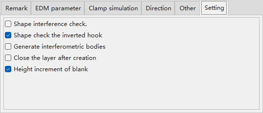
- Electrode Feature Interference Check: Check for interference between the electrode feature and the part
- Electrode Feature Undercut Surface Check: Check whether the electrode feature has an undercut surface
- Close Layer After Electrode Creation: Automatically close the electrode’s layer after the electrode is created
- Standard Blank Height Increment: Use the standard blank height increment
Special-Shaped Electrode
- Special-Shaped Electrode: Used to add attributes to special-shaped electrodes
- Select Centering Method: Choose from standard electrode, single-side reference electrode, multi-axis linkage (surface selection), lathe electrode, and square block electrode (point selection)
- Reference Plane: Define the reference plane of the electrode
- Reference Side Surface: Define the side surface of the electrode; the electrode centering method is automatically identified based on the reference side surface
Edit Special-Shaped Electrode
- Edit Special-Shaped Electrode: Modify electrodes with attributes; automatically read existing related attributes such as electrode number, gap, and quantity
Electrode Discharge Direction
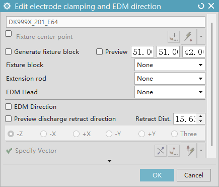
- Electrode Discharge Direction: Used to edit electrode clamping information and adjust the EDM direction
- Fixture Center Point: Define the fixture center point (correction for original text error: not surface roughness, but fixture center point) for label output (supports system parameters to set default value)
- Generate Fixture Block: Define the fixture center, generally used for eccentric electrodes
- Preview: View the fixture model or custom block
- Clamping Block: Select the simulated clamping block
- Extension Rod: Select the simulated extension rod
- EDM Spindle Head: Select the simulated EDM spindle head
- Electrode Discharge Direction: After activating the discharge direction, it can be modified to -Z, -X, +X, -Y, +Y, Three (3-axis direction)
- Preview Discharge Retract Direction: View the electrode retract position
- Retract Distance: Set the electrode retract distance
Multi-Body Electrode
Import from Other Plugins
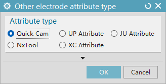
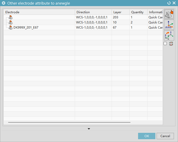
- Applicable to: Batch import "A Niu Attributes" (attributes from a specific plugin) from other plugins
- Select Other Electrodes: Add electrodes that need conversion
- Set WCS to Absolute Coordinate: Align the Work Coordinate System (WCS) with the absolute coordinate
- Coordinate Orientation: Specify the electrode to orient the WCS
- Close Electrode Layer After Completion: Close the electrode’s layer after the process is completed
Electrode Information
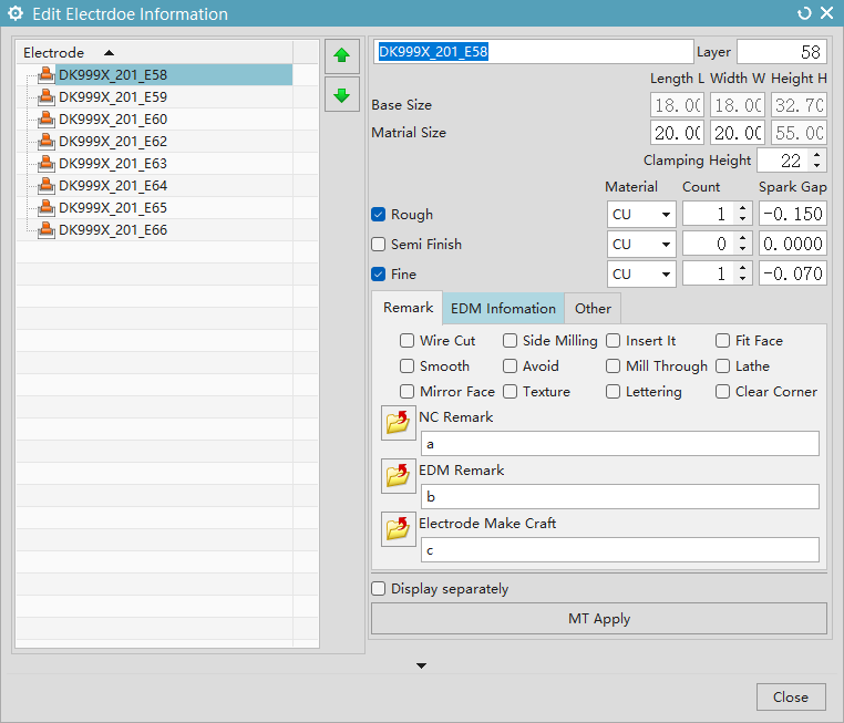
- Applicable to: Editing the content of electrode information
- Display Individually: Display the selected electrode individually
- Apply: Confirm the modifications
Electrode Renaming
Applicable to: When producing the same molds, batch change the electrode numbers. 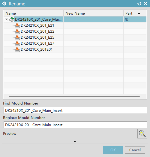
- Component: Electrodes with exported Part files
- Find: String to locate electrode and mold numbers
- Replace: New string for electrode and mold numbers
- Renaming scope: Electrode attributes, electrode entity names, electrode layer names, electrode drawing names/attributes, electrode extraction drawing attributes, exported electrode Part file attributes, entity attributes/names
Batch Electrode Number Modification
Applicable to: Reordering after discontinuous numbering or electrode deletion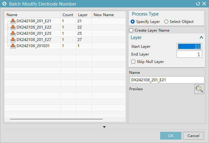
- Modification type - Specified layers: Loads all electrodes by default, renames sequentially from start to end layers with continuous incremental numbering
- Skip empty layers: Ensures consecutive electrode numbering
- Create layer name: Generates eponymous layer in electrode's parent layer
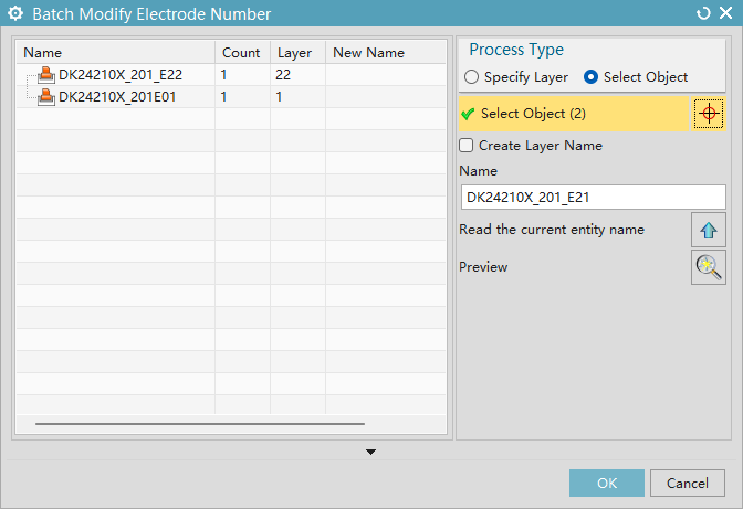
- Modification type - Selected objects: Renames chosen electrodes starting from specified name with incremental numbering, supports reading default names from selection and previewing new names
Mirror Electrodes
Applicable to: Electrode design for mirrored molds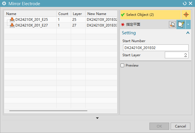
- Select objects: Electrodes to mirror
- Specify plane: Mirror reference plane
- Start number: Initial numbering for new electrodes (auto-increments)
- Start layer: Initial layer for new electrodes (auto-increments)
- Preview: Real-time mirror effect preview