
Electrode design
RibStrengthenTop
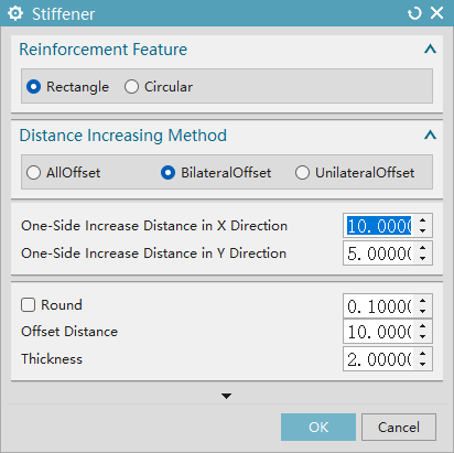
Reinforcement Shape:
- Rectangle: Select to create a rectangular-type reinforcement rib and activate subsequent parameters such as distance enlargement and thickness.
- Circle: Select to create a circular-type reinforcement rib and adjust the parameter configuration logic accordingly.
Distance Enlargement Method:
- Enlarge All Sides: Perform distance enlargement on all sides of the reinforcement rib.
- Enlarge Both Sides: Perform distance enlargement on both sides of the reinforcement rib.
- Enlarge Single Side: Perform distance enlargement on one side of the reinforcement rib.
- Enlargement Distance: Set the specific value for the distance enlargement of the reinforcement rib.
- Fillet: When checked, the "fillet" function is enabled, and the fillet radius can be set in the input box on the right; when not checked, the edge of the reinforcement rib is right-angled.
- Offset Distance: Set the offset position parameter of the reinforcement rib.
- Thickness: Set the thickness parameter of the reinforcement rib itself.
RibStrengthenSide
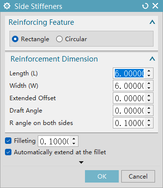
Reinforcement Shape:
- Rectangle: Select to create a rectangular-type rib reinforcement, and activate the input for parameters "Length (L)" and "Width (W)" simultaneously.
- Circle: Select to create a circular-type rib reinforcement; the "Length (L)" and "Width (W)" parameters will be automatically hidden, and the input for "Diameter (D)" will be activated.
Reinforcement Dimensions:
- Length (L): Set the length parameter of the rib reinforcement itself.
- Width (W): Set the width parameter of the rib reinforcement itself.
- Diameter (D): Set the diameter parameter of the rib reinforcement itself.
- Extension Offset: Set the extension offset parameter of the rib reinforcement.
- Draft Angle: Set the draft angle parameter of the rib reinforcement.
- Radii on Both Sides: Set the parameters for the radii on both sides of the rib reinforcement.
- Fillet: When checked, the "Fillet" function is enabled, and the fillet radius can be set in the input box on the right; when not checked, the edges of the rib reinforcement are right-angled.
- Auto-Extend at Radius Positions: When checked, the radius positions of the rib reinforcement will be automatically extended.
SplitBodyPoint

- Create a division plane by specifying a point and the Z-axis direction of the current WCS (Work Coordinate System), and use this plane to divide the selected body

SplitBodyThreePoints

- Create a division plane by three points specified by the user, and use this plane to divide the selected body
SplitBodyFaceOrPlane

Use the selected face (plane, cylindrical surface, conical surface) as a division tool to divide the body to which the face belongs
Example: Cylindrical Surface
Example: Planar Surface
OnlyLineSplitBody

- Create an extrusion feature by the line drawn by the user, and use this extruded body to divide the selected body
RectangleSplitBody

- Create an extrusion feature by the rectangle drawn by the user, and use this extruded body to divide the selected body

FlattenCurveFace

- Allow the user to select one or more surfaces, automatically extract the boundary curves of these surfaces, project them along the Z-axis direction of the current work coordinate system onto a plane associated with WCS, and finally generate a flattened curve
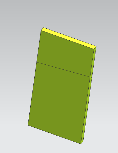
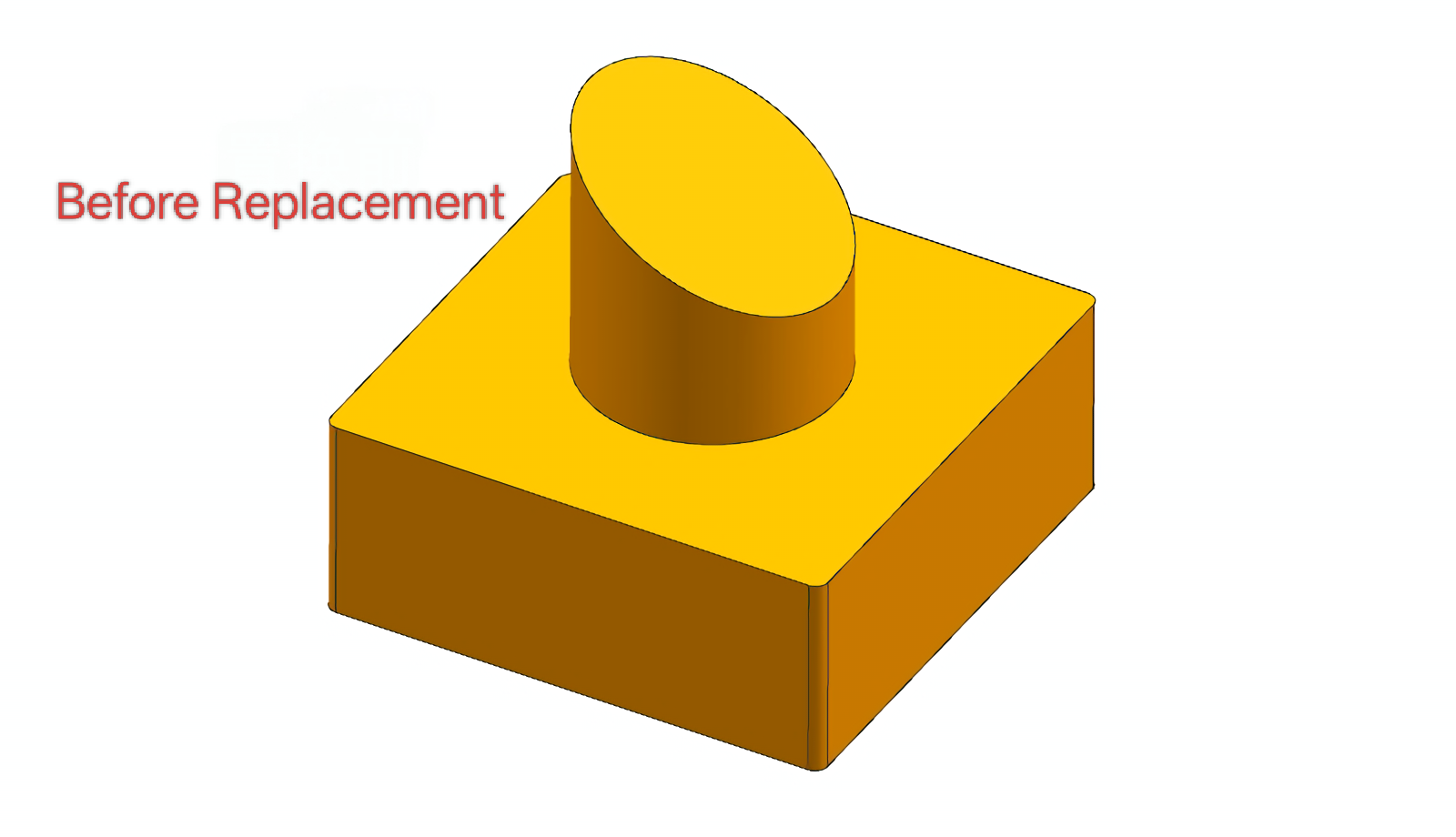
ReplaceFlatFace

- Replace the irregular surface on the product with a flat plane to simplify subsequent processing or assembly
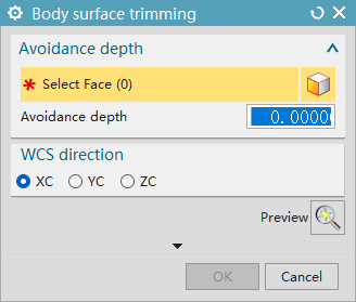
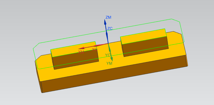
AvoidingBottomHole

- Create a clearance groove with a specified depth at the bottom of the hole structure to avoid interference between the machining tool and the hole bottom, or reserve assembly clearance

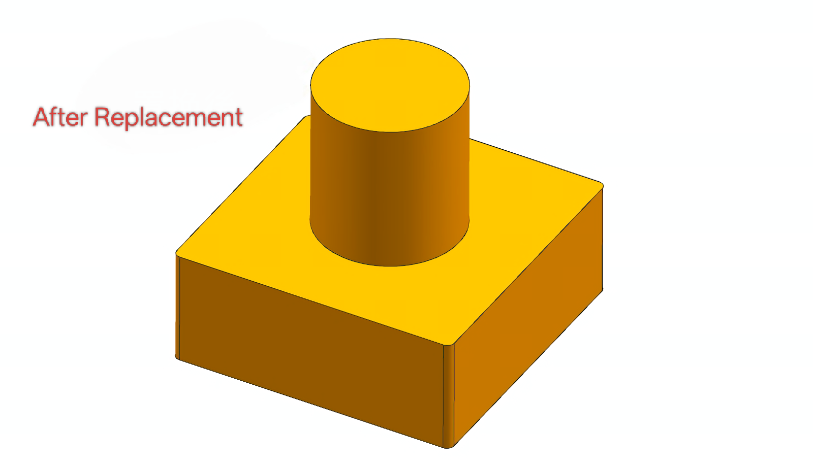
ElectctrodeCheckResult2DToJvMms

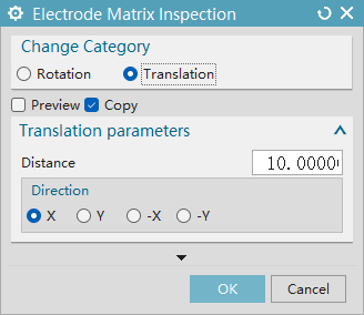
- Rotation: Set the rotation angle
- Translation: Set the translation distance
- Preview: View the effect
- Copy: Copy the entity to generate a new entity; delete the original entity and replace it with the new entity
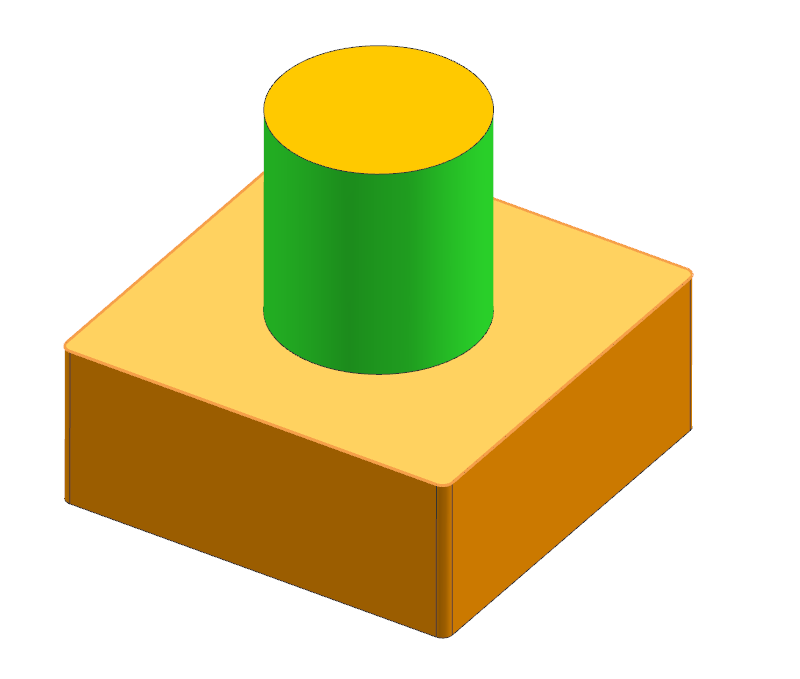
Create electrode body
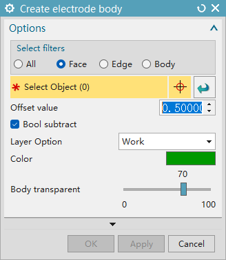
Selection Filter
- All: All types of objects can be selected to create the electrode body;
- Face: Only face-type objects can be selected for creation;
- Edge: Only edge-type objects can be selected for creation;
- Body: Only body-type objects can be selected for creation.
Object and Offset
- Select Object: Used to pick the target object for creating the electrode body;
- Offset Value: Set the offset parameter of the electrode body, the current value is 0.5000.
Boolean Operation and Layer
- Boolean Subtraction: Enable Boolean subtraction when checked;
- Layer Option: Select the layer where the electrode body is located, currently set to the "Working" layer.
Display Settings
- Color: Set the display color of the electrode body, currently green;
- Body Transparency: Adjust the transparency of the electrode body via a slider (range: 0 to 100), current value is 70.
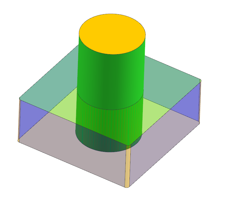
CreateElectrodeCylinder
Selection Filter
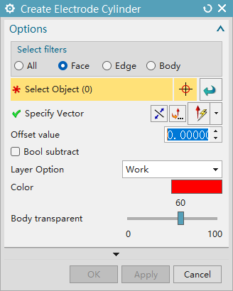
- All: All types of objects can be selected to create an enclosing cylinder.
- Face: Only face-type objects can be selected for creation.
- Edge: Only edge-type objects can be selected for creation.
- Body: Only body-type objects can be selected for creation.
Object and Vector
- Select Object: Used to select the object for creating the enclosing cylinder.
- Specify Vector: Used to specify the vector direction of the enclosing cylinder.
Offset and Layer
- Offset Value: Set the offset parameter of the enclosing cylinder, which can be adjusted by entering a value.
- Boolean Subtraction: Enable Boolean subtraction when checked.
- Layer Option: The layer where the enclosing cylinder is located can be selected, and in the example, it is the "Working" layer.
Display Settings
- Color: Set the display color of the enclosing cylinder, which is red in the example.
- Body Transparency: Adjust the transparency of the enclosing cylinder through a slider, with a range from 0 to 100.